

CNC Milling Parts Manufacturing What Designers Need to Know About Precision
2026-11-19
Precision in CNC milling isn’t a spec to check at the end—it’s the difference between a part that fits and a costly iteration. Yet many designers only discover the gap between a CAD model and a machinable part after quoting. This guide breaks down what actually drives accuracy, from tolerance stack-ups and tool geometry to material stress, so you can design for manufacturability before it becomes a production issue. At Tianyu, these are not abstract concerns; they are the details our engineers resolve every day on the shop floor.
Tolerances Are Negotiable Until the Tool Touches Metal
Before a job reaches the shop floor, tolerance boxes on a print are still up for debate. A designer might think calling out ±0.002 inches everywhere shows rigor, but a machinist reading the same drawing sees extra setups, slower feeds, and a quote that is about to balloon. Those early exchanges over redlines and phone calls are rarely polite in the way corporate emails are polite; they are direct because both sides know this is the only moment the numbers can move without consequences. Loosen one feature from a press fit to a clearance fit, add a datum that can actually be fixtured, and the part becomes something a shop can reliably make.
Once the end mill starts cutting, that flexibility disappears. The tolerance stops being a discussion point and becomes a physical requirement measured by the machine, the tool deflection, and the temperature in the room. A missed dimension cannot be negotiated back into tolerance; it can only be reworked, scrapped, or shipped with a concession. That is why veteran machinists push back hard before the first op. After chips start falling, the negotiation is over; the only conversation that matters is between the tool and the metal, and everyone else is just waiting for the inspection report.
Material Choice Sets the Ceiling for Precision
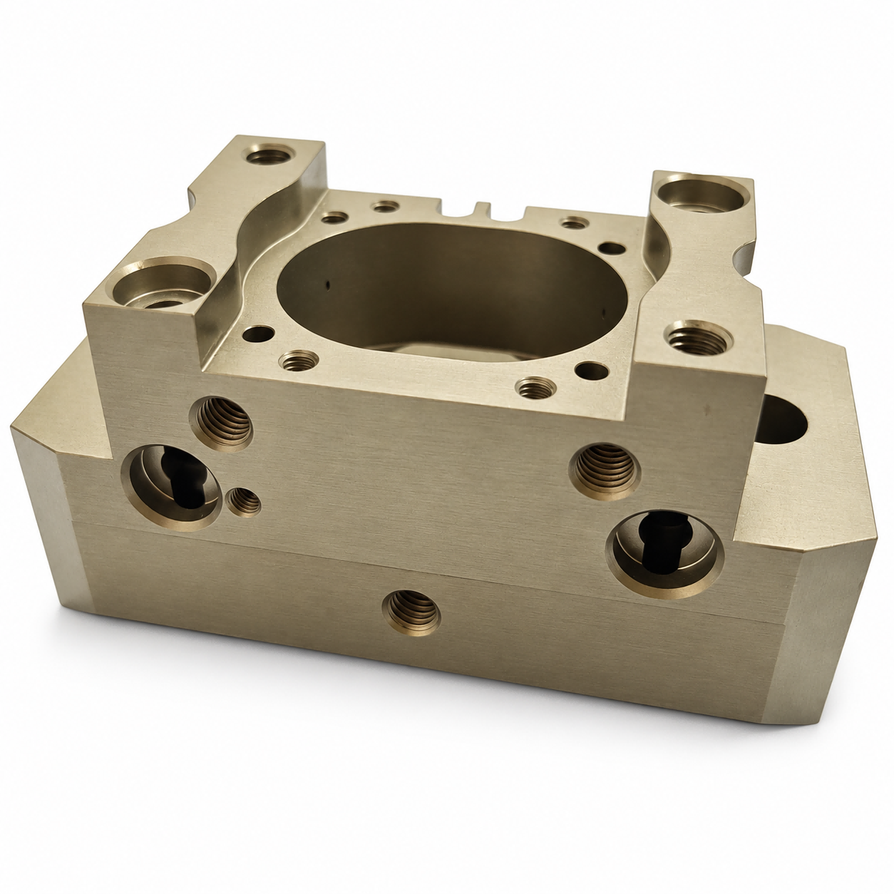
Precision work often gets framed around spindle runout, feedback resolution, and tool deflection, but the raw material has already placed a ceiling on the final result. Every alloy and composite carries its own thermal drift, internal stress, and damping behavior. Once a material starts moving a few microns on its own, no servo loop can tell the difference between thermal expansion and a positioning error, so the achievable tolerance quietly saturates.
This is why stable machine bases and inspection fixtures are not built from whatever stock is available. Cast iron, granite, Invar, and certain ceramics earn their place because they resist the slow dimensional wandering that ruins tight measurements. A material that relaxes after machining or swells with room temperature will keep stealing tolerance no matter how carefully the process is controlled.
Choosing a material then becomes an act of matching stability to the tolerance band rather than chasing an absolute property. A lightweight aluminum setup may hold ±0.1 mm all day, but pushing toward ±0.005 mm usually forces the conversation toward denser, stiffer, or thermally quieter options. If the material ceiling is lower than the target, the rest of the process only refines a part that was already limited before the first cut.
Tool Reach Decides What Geometry Can Actually Be Cut
A machine might list an impressive maximum cutting diameter, but the actual workable shape is often limited long before that number is reached. Deep pockets, narrow slots, and internal corners force the cutter into positions where the tool body or holder collides with the part. What looks possible on a flat drawing becomes impossible once the reach of the tool is measured against the wall height and corner radius. In many cases, the longest reach required by a feature is the real constraint, not the overall part envelope.
Tool reach changes how a job must be approached. A shallow feature can be cut with a short, stiff end mill, allowing aggressive feeds and clean finishes. The same profile sunk deep into a pocket demands a long, slender tool that vibrates, deflects, and wears unevenly. To compensate, programmers slow the spindle, reduce step-over, and take lighter axial passes. Even then, the result is rarely equal to what a shorter tool would produce. The extra clearance needed around the cutter also forces the design to accept larger fillets or additional finishing passes with a different tool entirely.
In practice, the reach limit pushes decisions upstream. A designer may assume any internal corner can be machined, but the shop must verify the longest tool length available and the diameter capable of surviving that extension. If a pocket drops below a certain depth-to-diameter ratio, the only practical options are to split the part, use a specialized long-reach tool, or redesign the feature. Ignoring this physical limit leads to scrapped parts, burned-up cutters, and hand-finishing work that was never accounted for in the quote.
Sharp Internal Corners Are a Design Habit Worth Breaking
Most designers pick sharp internal corners without thinking. It looks cleaner on screen, and CAD software never complains. But the real world does. A square inside corner concentrates stress exactly where a part is already weakest, and it makes cutting, molding, or printing far more awkward than it needs to be.
A small radius or relief changes the math in your favor. It spreads load instead of letting a crack start, reduces tool wear, and can even shorten cycle times. You don't always need a huge fillet; just enough to break the harsh intersection often turns a fragile detail into a durable one.
The habit is worth breaking because it forces you to think about how the part will actually be made and used, not just how it looks in a feature tree. Once you start catching these corners early, the downstream fixes and rejected parts quietly disappear.
Surface Finish Specs Often Cost More Than They Improve
Ask a machinist what happens when a print calls for an 8-microinch finish on a bracket nobody touches after assembly. You will usually get a shrug before you get an explanation. On paper, moving from a 32 to a 16 Ra sounds like a small edit, but in the shop it can mean a second operation, a different insert or wheel, slower feeds, and a lot more time at the profilometer. None of that is free, and most of it never changes how the part performs.
Some surfaces really do need tight finish control: seal faces, bearing journals, pump housings, and gasket flanges. The problem is that many drawings carry low roughness values out of habit, because someone copied an old spec or assumed smoother is always safer. A quick check against actual function often shows that a standard machined finish would have been just as reliable. If the surface does not slide, seal, or mate under load, paying for extra lapping or grinding is usually pure overhead.
A cleaner approach is to leave the tight numbers for faces that actually work for a living. Call out the critical areas and relax the rest. Let the shop use normal speeds, standard tooling, and ordinary inspection methods. The savings in cycle time, tool wear, and scrap tend to outweigh the barely measurable performance gain from chasing a shinier finish.
Designing Once for Prototype and Production Runs
A single board layout can serve both prototype and production if you stop treating the prototype as a throwaway. Put the programming and debug headers on the same board but leave them unpopulated in the final assembly, so the exact same panel comes off the line for both uses. This removes the usual handoff where a hacked bench version gets redrawn and quietly introduces new faults.
Make the prototype-friendly choices that don't hurt volume cost. Larger test pads near power rails, a few spare GPIOs broken out to a non-critical connector, and a boot mode jumper cost almost nothing on the BOM but save hours when firmware refuses to start on the first boards. At the same time, check that every component you specify has a second source or at least a realistic lead time for the production quantity.
The real discipline is avoiding changes after the first batch. If a part is too small to hand-solder during bring-up, don't swap it for a larger package later. Instead, adjust the stencil and reflow profile so the production process itself remains stable, and keep one documented set of files from the prototype order to the final release.
FAQ
Stick with standard tolerances like ±0.005 in for most features and reserve tighter bands for bores, bearing seats, or mating surfaces. Every decimal place you tighten usually adds at least one extra setup or a slower finishing pass, so ask which dimensions actually control assembly or performance. If a feature can live with ±0.010 in, saying so on the drawing gives the shop room to run efficient toolpaths instead of babysitting a noncritical edge.
A rotating end mill always leaves a radius in an internal corner, so a square corner forces the shop to switch to a broach, EDM, or hand work, or to redesign the pocket with a relief. Even a small corner radius, such as 0.030 in or 0.060 in, lets a standard cutter reach the corner in one pass. If a mating part has a sharp edge, add an undercut or clearance notch instead of asking the milling process to do something it cannot naturally produce.
Tolerance controls size and position; surface finish controls texture, waviness, and how the part feels or seals. You can hit a tight size with a rough finish or a smooth finish with a loose size. Calling out both on the same feature forces a shop to balance roughing and finishing cuts carefully. Specify the finish only where seal faces, bearing journals, or cosmetic surfaces need it, because an unnecessarily fine finish can add polishing or extra semi-finishing passes.
When you cut away material, internal stresses from rolling, casting, or prior heat treatment can release unevenly and warp the part. This shows up as dimensions drifting after the part leaves the fixture. Choosing stress-relieved stock, avoiding extreme wall thickness changes, and leaving enough material for a light finishing pass after roughing all help. For critical parts, plan for a rough machine, stress relief, and finish machine sequence rather than trying to hold a tight size in one setup.
Use 5-axis when angled holes, compound angles, or undercut geometry would otherwise require multiple fixtures and risk misalignment between setups. It is also worth it when a part has contoured surfaces that need smooth blending without visible step-over lines. For a simple bracket with one angled hole, a custom soft jaw or sine plate on a 3-axis machine may be cheaper. The choice is not about machine count; it is about how many datum shifts you can tolerate.
Mark the datums as the same surfaces that locate the part in the first operation, and use geometric tolerancing for position, profile, or runout only where function demands it. Add notes for broken edges, minimum corner radii, and whether a surface can show tool marks. If a hole is for clearance, say so instead of leaving a generic tolerance. The less a shop has to infer, the fewer phone calls and revised quotes you will get.
Thin walls flex under cutting pressure, vibrate, and can spring back after the tool passes, so the machined size may be different from what the tool path intended. Adding a little thickness, leaving temporary ribs for support, or specifying the finish pass at a lower depth of cut helps. A wall that is too thin can also distort during clamping, which means the part measures fine in the fixture but not after release.
Whenever possible, keep features that must align with each other in the same setup. Every time a part is unclamped and re-fixtured, a new datum relationship is introduced. If you have to split operations, define a common datum scheme on the drawing and make sure the fixture repeats on those same surfaces. This reduces stack-up error and keeps a shop from aligning to a rough cast surface or a nonfunctional edge.
Conclusion
Designers often treat tolerance callouts as flexible until the first setup begins, but that window closes quickly once a cutter engages the stock. The alloy or plastic chosen also sets a hard limit on what precision is realistic—no amount of careful programming can fully compensate for a material that moves unpredictably under heat or stress. In the same way, tool reach determines whether a deep pocket or narrow rib can be machined at all, not just how slowly it will run. A design that ignores reach often forces unnecessary EDM work or awkward setups. Sharp internal corners deserve similar scrutiny: a nominal 90-degree corner is rarely practical because a rotating end mill leaves a radius, and trying to force zero radius only adds cost and complexity.
Surface finish specifications are another area where designers overspecify without always understanding the downstream effect. Calling out a very fine finish across non-functional faces can double or triple finishing time while adding little to performance. Instead, reserving tight finishes for sealing faces, bearing journals, or cosmetic surfaces keeps costs in check. Finally, the gap between prototype and production is often smaller when the design anticipates the limits of standard tooling from the start. If a prototype requires special cutters or unusual workholding, those choices tend to echo into every later run. A part designed once for both stages—using realistic tolerances, reachable geometry, suitable materials, and only the necessary finishes—survives the transition with fewer changes and fewer surprises.
Contact Us
Contact Person: Vera Yao
Email: [email protected]
Tel/WhatsApp: 8618512832770
Website: https://www.tianyucnc.com