

Complete Cylinder Head Maker for Reliable Engine Performance
2026-11-16
Cylinder heads are where an engine’s reliability is won or lost. A complete head, machined right and assembled with care, can transform an average rebuild into a bulletproof runner. That's exactly the standard DDR builds to—and it's why so many engine builders turn to their complete cylinder heads when performance can't be left to chance. Before we dive into the specs and real-world results, ask yourself: is your current head supplier actually engineering for the long haul, or just casting to a price? The difference shows up in every heat cycle.
Chamber Volume Matching for Balanced Compression
In any reciprocating engine or compressor, cylinder-to-cylinder compression consistency starts well before the first firing stroke. Chamber volume is rarely identical across production units; casting shifts, deck heights, valve seat depths, and even piston dish machining all stack up. A half-cc difference might look trivial on a worksheet, yet at cranking speed or under boost it translates into a measurable spread in dynamic compression.
The practical approach is to measure every chamber with a burette and a flat plate, then sort or lightly machine until the tightest group falls within a narrow band, often under 0.3 cc for high-strung builds. Some builders go further and match head chamber volumes to actual piston dome or dish volume, indexing piston pin height and rod length so the total trapped volume at TDC stays within a whisper of the reference cylinder. Surface finish and seat blending matter here too; a small ridge or unblended cut can hold a droplet and skew the reading.
Once volumes are matched, the engine responds with more even cylinder pressures, which shows up as steadier cranking signatures, reduced main bearing pounding on the weak cylinder, and a calmer torque delivery near knock limit. It is quiet work that never appears on a spec sheet, but it separates engines that merely run from ones that pull cleanly across the whole rev range.
Port Profiles Developed on a Wet Flow Bench
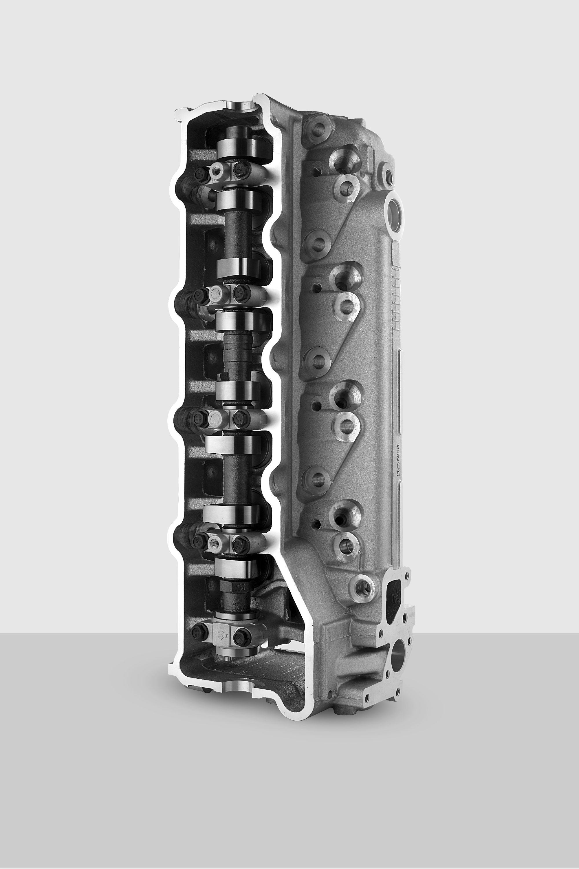
Shaping a port on a wet flow bench is a hands-on process where liquid mist or dye injection exposes exactly how fuel and air behave inside the runner. You quickly learn that a port that flows big numbers on a dry bench often falls apart when wet—fuel gathers in dead zones, the short-side radius sheds the liquid film early, and low-lift flow becomes turbulent and unpredictable. The bench lets you trace those wetting patterns directly and reshape the port floor, bowl, and valve seat blending until the liquid follows the wall without breaking away or pooling.
Most of the real gains come from chasing discharge coefficient improvements at valve lifts below 0.300 inch, not just peak lift. A slight change in the guide boss or a smoother transition from the seat into the throat can keep the fuel suspended longer, which shows up on the wet bench as a thin, even film rather than heavy droplets drifting into the chamber. These subtle adjustments rarely move the peak flow number by much, but they make a measurable difference in part-throttle response and cylinder-to-cylinder consistency. Some builders will run back-to-back tests with different valve seat angles or chamber entry profiles, watching how the mist behaves through a clear cylinder sleeve.
The finished port profile is really a compromise between volume, velocity, and mixture quality. A well-developed wet flow port might give up a few cfm at maximum lift compared to a dry-bench hero shape, yet it idles cleaner, pulls harder from low rpm, and reduces the chance of puddling during cold starts. For anything driven on the street or run in endurance conditions, developing the profile on a wet bench beats relying on dry flow numbers alone every time.
Valve Seat Materials and Multi-Angle Grinding
Cast iron seats with induction-hardened contact faces remain a workhorse in production engines, but they behave very differently from the cobalt-chromium overlays found in heavy-duty diesel heads. The harder Stellite-type alloys resist recession and micro-welding at high temperatures, yet they also punish cutting tools more severely. In contrast, ductile iron and even copper-beryllium seats trade some wear resistance for better heat transfer away from the valve face, which can be exactly what a turbocharged street engine needs. Choosing a seat material is not about finding the hardest option; it is about balancing thermal conductivity, machinability, and long-term seat width stability.
Multi-angle grinding moves beyond a single 45-degree contact cut by adding a narrower top angle (typically 30 or 15 degrees) and a deeper throat angle (60 or 75 degrees). The goal is twofold: concentrate the seating load on a thin, well-defined ring and smooth the transitions where airflow turns sharply. A classic three-angle job might leave only 0.040 to 0.060 inch of actual 45-degree face, with the top cut preventing a sharp ledge and the throat cut blending into the bowl. On iron seats this is straightforward with stones; on hardened overlays it usually requires diamond or CBN tooling and a rigid pilot to keep all three angles concentric.
The interaction between seat material and multi-angle grinding shows up most when you check runout. Softer cast iron will deflect slightly under stone pressure and may cut eccentric if the pilot flexes, while a hard Stellite seat tends to chatter unless you reduce speed and increase stone dressing frequency. Because multi-angle seats rely on a narrow contact band, any runout becomes more critical; you cannot hide it with a wide single 45-degree face. A careful machinist will adjust grinding pressure, coolant flow, and the order of cuts to match the material, sometimes leaving the throat angle slightly rough to help atomize fuel rather than polishing it to a mirror finish.
Thermal Stress Relief Before Final Machining
Residual stresses trapped inside a workpiece can quietly distort dimensions once material is removed. That is why many shops choose to run a thermal stress relief cycle before final machining. By heating the part to a controlled temperature below its transformation range and then cooling it slowly, the material gets a chance to relax. This step helps prevent unexpected movement during the last passes, where tolerances are tight and there is little room for correction.
The exact soak time and temperature depend on the alloy, but the principle stays the same: let the metal settle before you cut it to size. Skipping this operation might save a few hours early on, but it often costs more later when a finished component warps out of spec. For complex geometries or parts with large welded sections, stress relief becomes less of an option and more of a necessity.
In practice, some machinists treat this as a form of insurance. You do not always see the benefit on a simple bracket, but on a long, thin housing or a precision-machined plate, the difference is obvious. Once the part has gone through the cycle, subsequent machining behaves more predictably, and the final inspection results are far more consistent.
Leak Testing Every Head Before It Leaves the Shop
Every cylinder head that comes through our shop gets a dedicated leak-down test before it's boxed up. We don't sample-test or assume the machining was perfect—each one is pressurized and held to a specific tolerance. If a valve seat doesn't seal or a casting has porosity, we catch it right there on the bench, not after it's bolted onto an engine.
The process itself is straightforward but unforgiving. We use a calibrated leak-down tester with warm fluid, not cold air, because that's closer to real running conditions. The head is sealed on a flat plate, and we watch the gauge for any drop over time. Small leaks that would pass a quick bubble test show up clearly. That's the kind of detail that prevents comebacks.
It adds maybe ten minutes to each job, but we'd rather spend that time than ship something that costs a customer a head gasket failure down the road. The result is a part you can bolt on and trust the first time, not one that needs a second look after the fact.
Custom Fitments for Obsolete and Race Engines
Finding intake manifolds or bellhousings for a 1940s flathead or an early Cosworth DFV is rarely a matter of browsing a catalog. Off-the-shelf parts simply don't exist for many engines that were produced in limited numbers or raced before modern CAD archives. That's where custom fitments come in—each one measured directly from the block, head, or gearbox face to ensure a precise match rather than a hopeful approximation.
The process usually starts with a detailed scan or hand measurement of the original mounting points, followed by machining from billet or fabricating from steel or aluminum. Tolerances are often tighter than factory specs because race engines vibrate harder and run hotter than their road-going relatives. A well-made custom adapter can solve alignment issues that plague rebuilt obsolete engines, such as dowel pin drift or uneven flange surfaces.
Beyond simple adapters, this work covers throttle body spacers, dry sump pump brackets, and even one-off engine mounts for vintage race cars. The goal isn't to make a showpiece, but to keep an engine that has no parts support running reliably under load. For owners of obsolete or race-only powerplants, a custom fitment is often the difference between a permanent garage ornament and a working machine.
FAQ
It spans from raw casting inspection and CNC machining to valve seat installation, pressure testing, and final surface finishing. We don't outsource any critical step, so every dimension stays under our control.
We use thermal cycling and leak-down tests on every head, not just batch samples. The alloy mix is tuned for heat dissipation, and we machine the deck surface to a flatness tolerance of 0.05 mm to prevent gasket failures.
We stock cast iron for heavy-duty diesel applications, aluminum alloys like A356 and 319 for performance gasoline engines, and compacted graphite iron for high-boost turbo setups. Each material gets a dedicated machining strategy.
Yes, we keep a flexible CNC cell that switches between models in under two hours. For one-off race heads or restoration projects, we can reverse-engineer from a provided sample or CAD file.
Besides coordinate measuring machine inspection on critical bores and seats, we run a water jacket pressure test at 40 psi and a vacuum test on the valve seats. Any head that weeps or leaks gets scrapped, not reworked.
We avoid thin spots in the casting by working closely with foundries on wall thickness and core placement. After machining, we shot-peen the combustion chamber area to relieve stress and add a ceramic coating option for heat barrier.
We have a library of over 600 original patterns and can digitize a worn head if the pattern is missing. Minimum order for a discontinued model is typically five pieces, but we often keep common legacy heads in stock.
For a catalog cylinder head, we ship within 10 business days. Custom machining adds about two weeks, and complete reverse-engineering projects take four to six weeks depending on complexity.
Conclusion
Every cylinder head that leaves the shop reflects a commitment to precision that starts well before assembly. Chamber volumes are matched across the set so combustion stays even from cylinder to cylinder, a detail that prevents one hole from working harder than the rest. Port profiles aren't copied from a catalog; they're developed on a wet flow bench, where fuel behavior is studied rather than guessed at. That same attention carries into the valve seats, where material selection and multi-angle grinding shape the way air enters and exhaust leaves. Then comes thermal stress relief before final machining, a step that keeps dimensions stable long after the engine reaches operating temperature.
No head goes out the door without a leak test, because a small seepage on the bench becomes a big problem under boost or sustained load. That's the difference between a part that fits and a part that lasts. For builders working with obsolete or race engines, custom fitments are treated as the rule rather than the exception. If the original casting is long gone or the port layout needs to match an odd intake manifold, the shop adapts. Reliable engine performance isn't a single feature; it's the result of every one of these steps being handled with the same discipline.
Contact Us
Contact Person: Shelly
Email: [email protected]
Tel/WhatsApp: 8613967667688
Website: https://www.yongyu.com/