

ODM Flange Penstock Gate: Essential Guide to Design, Applications, and Maintenance
2026-11-02
Most ODM flange penstock gates are judged by their drawings, yet real failures show up weeks later at the flange face or the stem seal. That disconnect is exactly what this guide tackles. From design tolerances to field maintenance, we cut through the noise and highlight the details that keep water where it belongs. You'll also see why THT treats every gate as a system, not a commodity.
What Actually Goes Into Designing a Flange Penstock Gate That Lasts
Designing a flange penstock gate that actually lasts starts with a hard look at the loads it will face—not just the obvious hydrostatic pressure, but the cyclic vibration from opening and closing, water hammer spikes, and thermal expansion that can stress the flange joint. Material choice has to match the water chemistry; for instance, brackish or high-chloride service will eat through ordinary cast iron faster than expected, while ductile iron or duplex stainless needs compatible seal materials to avoid galvanic corrosion at the seating faces.
The flange connection itself is often where longevity is decided. Mating surfaces must be machined flat enough to compress the gasket evenly, yet even small field misalignment creates uneven bolt loads that eventually lead to weeping or flange cracking. Designers have to specify bolt torque sequences, gasket compounds like EPDM or PTFE laminates, and surface finish on the flange faces. Another often-overlooked detail is the clearance between the gate disc and the guide rails—too tight invites jamming under sediment load, too loose causes chatter that frets the seal seats.
Durability also hinges on serviceability. Replaceable seat rings, built-in lubrication ports, and fusion-bonded epoxy coatings outperform simple paint jobs by years. Drainage and sand-flushing grooves in the bottom track prevent silt from grinding the lower seal during partial openings. And one factor that gets missed repeatedly: the design needs to know how often the gate actually cycles. A gate that opens twice a day under load has a completely different fatigue life requirement for its stem and bearings than one that moves only during annual maintenance.
The Materials and Seal Choices That Make or Break Gate Performance
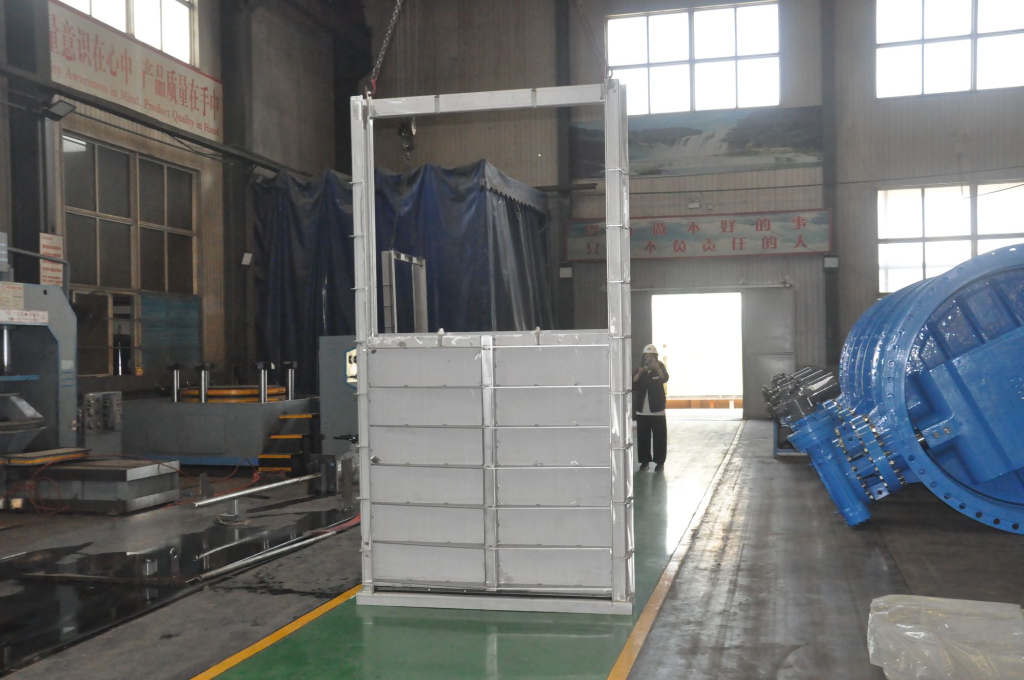
Most gate failures trace back to two overlooked decisions: the alloy under the bonnet and the elastomer squeezed into the seat. A 316 stainless wedge handles chloride-rich water without pitting, but pair it with a plain EPDM seal and you have capped the temperature ceiling at around 150°C. Swap to Viton and the same geometry suddenly tolerates aggressive hydrocarbons, though at the cost of low-temperature flexibility. The real trick is matching the seal's compression set and chemical compatibility to the specific flow media, not just the pressure rating printed on the valve body.
Hard-seat metal gates, often stellite-faced or nitrided, shine in slurries and high-cycle steam lines where soft seals would shred or extrude. But they demand precise lapping; even a 0.001-inch mismatch leaks. Conversely, resilient-seated gates forgive minor debris but become useless once the rubber swells or hardens from the wrong additive package. The best-performing installations treat material and seal selection as one system, testing both under actual cycling and thermal shock, because a gate that seals on day one can easily fail on day ninety if the elastomer takes a set or the metal galls under repeated operation.
Where These Gates Show Up in the Field and What They Handle
You'll spot these gates in places most people never look twice at—along pipeline runs, tucked inside pump stations, mounted on the sides of treatment basins. They're not there for show. Each one handles a specific slice of the process: flow rate, pressure, level, sometimes temperature. A gate on a cooling water line might throttle flow to keep a heat exchanger from overheating, while one on a sludge return line meters thick slurry without clogging. The environment dictates the design, and the design dictates what the gate can realistically manage before maintenance crews have to step in.
Move into a control room and you'll see the same logic playing out in ladder diagrams and function blocks. Here the "gates" are logical constructs—AND, OR, NOT, and their combinations—living inside PLCs and safety relays. They handle signals from limit switches, pressure transmitters, and emergency stop buttons, deciding whether a valve opens, a motor starts, or a conveyor halts. What they handle isn't physical fluid anymore but the truth values that keep a process from tearing itself apart.
The field versions and the control versions rarely get talked about together, but they're two halves of the same job. One manages the physical stuff, the other manages the decisions about that stuff. When a gate in the field fails, it's usually because it tried to handle something it wasn't built for. When a gate in the logic fails, it's because someone assumed the signal would always be clean. Both failures teach the same lesson: these gates show up where reality meets intention, and what they handle is the gap between the two.
How to Build a Maintenance Schedule That Fits Real-World Use
Most maintenance schedules fall apart because they assume perfect conditions: machines run exactly as rated, crews never skip a shift, and calendars stay fixed. Real-world use is messier. Start by observing your actual equipment patterns for a few weeks. Which units get pushed past recommended intervals because production demands it? Which checks are consistently ignored? Where do unexpected failures cluster? Use those observations as your baseline, not the manufacturer's idealized plan.
Build slack into the schedule so it can breathe. Instead of hard dates, set flexible windows like "every 30-45 operating hours" or "within five days after hitting 200 cycles." Give technicians the authority to adjust non-critical tasks if they log a short reason. Keep safety-related items on fixed dates, but let lubrication or filter swaps shift within reason. This prevents overdue pileups and makes the schedule feel like a reference tool rather than a constant source of blame.
Finally, review the schedule every month with the people who actually do the work, not just maintenance managers. Ask which tasks were done properly, which were pencil-whipped, and which machines still broke down anyway. Move low-value time-based tasks to condition-based triggers such as noise, heat, or vibration readings. A maintenance schedule that survives real-world use is never finished; it changes as soon as operators or failure data show a better pattern.
The Subtle Signs of Gate Wear That Most Operators Overlook
Operators tend to focus on the obvious breakdowns—bent hinges, cracked panels, or sagging corners. But gate wear often whispers before it shouts. Look closely at the bottom edge of the gate. A slight, uneven polishing of the metal where it grazes the ground during each cycle might seem like normal scuffing, yet it can reveal a developing misalignment in the post brackets. When the gate swings, does it pause imperceptibly halfway through its arc, as if catching its breath? That tiny hesitation often precedes a bearing failure by weeks. Another quiet signal: the latch plate develops a faint, crescent-shaped groove that wasn't there a month ago, indicating the gate's weight has shifted onto a single strike point. These are the details most people walk past every day without a second thought.
Beyond the mechanical, there are sensory clues that rarely make it into maintenance checklists. Run your hand along the top rail after the gate has been closed for an hour. A temperature difference between the hinge side and the latch side—warm near the hinges, cool at the latch—can point to internal friction building in one of the rollers. Listen during the first open of the morning when the gate is cold. A low, almost musical creak that fades after a few swings is not just annoying; it can signal that the grease inside the hinge pin has dried into a gritty paste, slowly lapping the metal away. Even the way dust settles on the gate tells a story. If you notice a fine, rusty powder accumulating at the base of one hinge but not the other, that's microscopic wear debris escaping from a failing seal. None of these signs will trigger an alarm on their own, but together they sketch a clear picture of a gate quietly grinding toward trouble.
The overlooked signs often live in the margins: the half-turn of a bolt that has loosened not from vibration but from the gate's own shifting weight, the faint ring of bare steel where a coat of paint has been rubbed away by a misrouted cable, or the way a gate leaf drifts an extra inch in the wind compared to last season. Pay attention to the angle of the diagonal brace. A change of just a degree or two can indicate that the gate frame is starting to parallelogram under its own load. Check the concrete pad beneath the gate's travel path. Hairline cracks radiating outward from the post bases, especially if they follow the direction of the gate's swing, often mean the anchor bolts are slowly being worked loose. These subtle signs don't scream for attention, but for an operator who knows where to look, they speak plainly enough.
Avoiding the Installation Pitfalls That Lead to Early Gate Failure
Many gate failures trace back to rushed installations where the post footing gets poured before the gate's full weight and swing arc are accounted for. A gate that feels solid on day one can start sagging within weeks once the hinges settle into soft ground or the post shifts under repeated movement. Instead of treating the footing as an afterthought, take time to dig below the frost line, use a wider base than the post diameter, and let the concrete cure fully before hanging the gate. A slight oversizing here costs a little extra effort but prevents the slow, invisible misalignment that eventually tears hinges out of wood or metal.
Another common trap is mounting hardware directly onto treated lumber without a moisture barrier, or choosing hinges rated for half the actual gate weight. Installers often forget that a gate acts like a lever—every kilogram of panel multiplies the force at the hinge point, especially on sloped ground or windy sites. Swap flimsy strap hinges for heavy-duty ball-bearing models, add a diagonal brace running from the top hinge side down to the bottom latch side, and check the clearance for ground obstructions before the first test swing. A gate that scrapes or binds during installation will only worsen as temperatures and soil moisture change.
Finally, avoid leaving the gate to hang on temporary supports while you fine-tune other parts of the fence. That overnight stress can permanently bend the top rail or loosen the post anchors. Instead, complete the gate's frame, hinges, and latch in one focused session, then verify the swing three or four times with the gate fully loaded. If the post moves even a few millimeters, stop and reinforce it rather than hoping the concrete will hold. Early correction is far cheaper than replacing a failed gate after a season of hard use.
FAQ
ODM stands for Original Design Manufacturer, meaning the supplier not only produces the gate but also handles the engineering design based on your specifications. This allows you to get a gate tailored to specific pressure ratings, flange dimensions, and operating conditions without maintaining an in-house design team.
The key parameters are the design head or pressure, the clear opening size, and the flange standard you need to match. You also need to decide the sealing direction—upstream or downstream—and whether the gate will be operated manually, with an electric actuator, or hydraulically.
They appear in irrigation canals, water treatment plants, reservoir outlet works, and industrial cooling water systems. Anywhere you need positive shutoff or flow control in a pressurized pipeline with flanged connections, a penstock gate can be a practical choice.
Plan for periodic lubrication of the stem and gearbox, inspection of the seal faces for debris or damage, and a check of the flange bolts for correct torque. If the gate sits in sediment-laden water, flushing the seat recess and verifying the wedge or slide movement under load should be part of the annual routine.
EPDM or nitrile rubber seals work for clean water and moderate temperatures, while harder polyurethane seals resist abrasion in sandy flows. For chemically aggressive water, you might need Viton or a metal-to-metal seal with a resilient insert, so the material choice directly affects leak-tightness and service life.
Yes, if the existing flange matches the gate's drilling pattern and pressure class. You may need a spacer or adapter ring if there's a slight mismatch in flange standards, but as long as the pipeline can be isolated and drained, installation is mostly a matter of aligning the gate, torquing the bolts, and testing the operation before returning to service.
Watch for sudden increases in operating torque, visible leakage past the seat when the gate is fully closed, or unusual vibration during pipeline flow. Any of those indicates the seal may be damaged, the stem could be bent, or debris is trapped in the guide rails—all of which warrant shutting down and inspecting the unit.
Yes, penstock gates are generally designed for low-head, large-opening applications with a rectangular or square flow area, while gate valves are round and better suited for higher pressures. You'd choose a penstock gate when you need to isolate an intake or canal with a compact, flange-mounted solution that can handle some debris without jamming.
Conclusion
A flange penstock gate that holds up over years starts with a clear-eyed look at the operating environment. Designers rarely settle for a generic slab; they match plate thickness, stem diameter, and reinforcement ribs to the actual pressure head, flow velocity, and how often the gate cycles. In water treatment plants and low-head dams, a lighter stainless steel gate with a resilient EPDM seal may be enough. For abrasive slurry or raw sewage bypass, however, cast iron bodies with bronze seating faces and a harder NBR or even metal-to-metal seal make far more sense. The flange connection itself needs the same attention: uneven gasket compression or a warped mounting surface will undo even the best material choices.
Maintenance that actually prevents failure is tied to duty cycles and water chemistry, not a calendar reminder. A gate opened twice a day in silty river water needs inspection far more often than one cycled monthly in clean service. Early wear often shows up quietly: a slight increase in handwheel torque, a faint line of pitting just above the seat, or a seal that no longer springs back when the gate is lifted. Operators who catch these signs avoid the deeper damage caused by misalignment or sediment packed into the bottom track. Installation mistakes are equally avoidable—over-tightening flange bolts, forcing alignment with a pry bar, or letting the gate hang unsupported before bolting up all create distortion that shortens seal life. Getting the gate to seat squarely, with the stem centered and the flange faces parallel, is the cheapest long-term reliability step.
Contact Us
Contact Person: Su Zhang
Email: [email protected]
Tel/WhatsApp: +86-25219206
Website: https://www.tht-valve.com/