
Zinc-Nickel Alloy Plating Equipment: Top 10 Solutions for Superior Corrosion Resistance
2026-11-02
Every year, corrosion costs industries billions—and most failures trace back to plating processes that were never designed for today's demanding environments. Zinc-nickel alloy plating changes that equation, offering substantially better protection than traditional zinc alone. But equipment choice makes all the difference. Here are the top 10 solutions from Junda that help manufacturers achieve superior, repeatable corrosion resistance.
Reading Bath Chemistry Before the First Rack Goes In
A surprising number of plating problems can be traced back to the first few minutes of the shift. Operators often rush to load the first rack without checking whether the bath has settled overnight, whether brightener levels drifted, or whether the pH shifted after a long idle period. Taking ten minutes to pull a sample and run a quick titration or Hull cell test can reveal issues that would otherwise show up as dull spots or uneven thickness hours later.
One thing that rarely gets mentioned is how temperature stratification plays into early-morning readings. The top layer of solution might read a degree or two warmer than the bottom, especially if the tank heater has been cycling on a timer. Stirring the bath gently before sampling—not just relying on the circulation pump—gives a more honest picture. If the bath has been sitting still for more than eight hours, a quick manual agitation with a clean paddle can break up any concentration gradients near the anodes or along the tank walls.
Also worth checking before that first rack: the condition of the filtration system and the level of dissolved solids. A clogged filter bag won't ruin the bath overnight, but it will slowly starve the solution of fresh flow, and that first rack often gets the worst of it. Logging these early readings, even just a line in a notebook, builds a baseline that helps spot slow drifts before they become scrap. It's not glamorous work, but it beats explaining to a customer why their order has a haze pattern right out of the gate.
Matching Rectifier Ripple to Part Geometry and Load Size
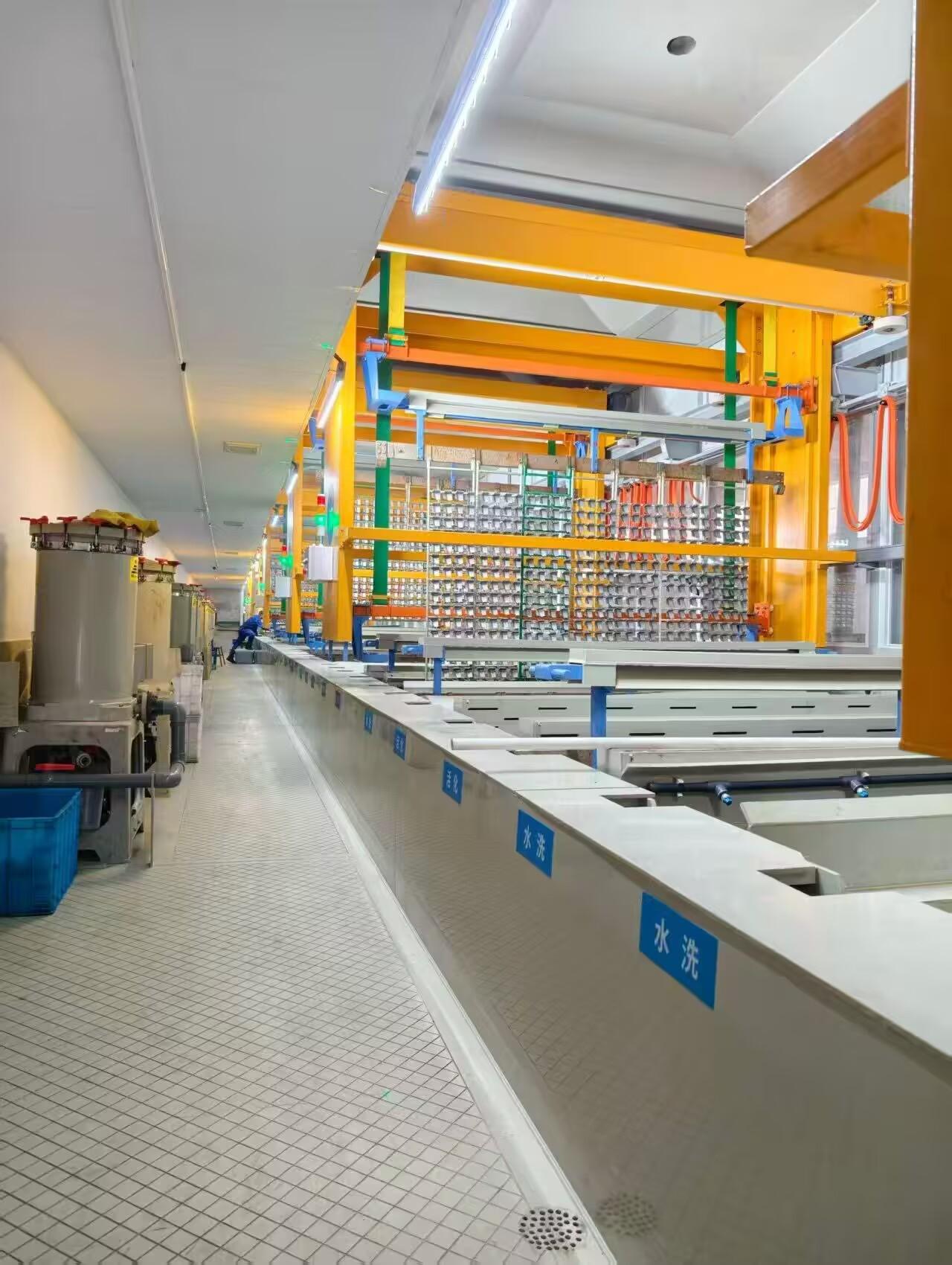
Rectifier ripple is rarely a one-size-fits-all setting. When you plate a deeply recessed bore or a part with sharp corners, the local current density can spike well above the average, and high ripple makes those spikes worse. A low-ripple output keeps the deposition more uniform across intricate geometry, while a flat panel of the same surface area may tolerate a higher ripple percentage without visible defects. That means the acceptable ripple level has to be checked against the actual shape in the tank, not just the rectifier's nameplate rating.
Load size changes the picture again. A rectifier sized for a large barrel or rack will often run at a small fraction of its rated current when you switch to a handful of small parts. Under those light-load conditions, ripple percentage frequently climbs because the output filtering was designed for full load. You may need to add capacitance or reduce the rectifier's output range to hold ripple down. Conversely, a heavy load with low resistance can smooth the output slightly, but it also demands more current, so the ripple's effect on edge buildup and burning becomes more critical.
The practical fix is to match the rectifier's filtering and control response to the combination of part geometry and anticipated load range. Measure ripple at the bus bar with the actual parts in place, not in a bench test, and adjust the output stage or add external filtering until the waveform suits the most sensitive area of the job. For complex shapes or very small loads, a three-phase or switch-mode rectifier with low residual ripple usually pays for itself in fewer rejects and less hand buffing.
Why Anode Placement Changes Coverage More Than Chemistry Tweaks
The geometry of the anode relative to the cathode dictates the primary current distribution, which directly shapes where deposition or corrosion occurs. Even slight shifts in anode position alter the path of least resistance for ions, creating localized high-current-density zones that no additive concentration can fully override.
Chemical tweaks—like adjusting brightener or suppressor levels—mostly influence the secondary current distribution by changing polarization behavior at the electrode surface. While these additives can smooth out microscopic roughness or refine grain structure, they cannot compensate for a fundamentally uneven macroscopic field caused by poor anode placement. A misplaced anode leaves large areas starved of current, a problem that chemistry alone cannot mask.
In practice, operators often chase coverage issues with bath modifications, only to find that a simple anode repositioning yields a dramatic improvement. Because current follows geometry first and chemistry second, optimizing anode placement provides a more direct and robust lever for uniform coverage than any incremental adjustment to the electrolyte formulation.
Filtration Layouts That Keep Zinc-Nickel Baths Free of Metallic Fines
Fines in a zinc-nickel bath rarely stay suspended long enough for a single mid-depth inlet to grab them. Most settle into corners or behind anode baskets, where the bath's normal circulation never reaches. A layout that works pulls from the tank floor through a manifold of pickups spaced no more than 12 inches apart, then returns filtered solution through a perforated sparger along the opposite wall. That crossflow pattern keeps the bottom swept and carries heavy particles into the strainer instead of letting them pile up.
Filter media selection should match the particle size that actually causes defects, not just the nominal rating on a data sheet. For zinc-nickel, a two-stage setup works better than a single fine cartridge. A coarse basket or bag ahead of the pump removes larger metallic chips before they can damage impeller surfaces, while a depth-style cartridge rated at 5 microns absolute catches the fine iron and nickel particles that create rough deposits. If the bath uses soluble nickel anodes, that first stage loads quickly, so placing differential pressure gauges across each housing gives you a visible cue for change-outs.
Pipe routing also decides whether the system filters the whole bath or just a narrow loop. Avoid short-circuiting by locating the filter pump suction far from the return line. Sizing the return flow to about two to three bath turnovers per hour can keep fines in motion without stirring up settled sludge. In rectangular tanks, two nozzles near the bottom corners aimed toward the pickup manifold create a slow rolling current that works better than strong surface agitation, which tends to push fines into dead zones.
Managing Drag-Out Without Overloading the Waste Treatment Line
Drag-out is an unavoidable byproduct of surface finishing, but letting it spiral into the waste treatment system can quickly turn a manageable bath into a chemical headache. The trick lies in catching the problem at the source, before rinses ever reach the treatment line. Simple mechanical fixes like extended drip times, strategic racking angles, and air knives or spray rinses directly over the process tank can reclaim a surprising amount of solution. These low-tech steps don't just cut waste volume—they also stretch the life of your plating bath and reduce the load on downstream neutralization and precipitation stages.
Another layer of control comes from smart rinse design. Counterflow rinses, where fresh water enters only at the final stage and moves backward against the work flow, concentrate drag-out in the first rinse tank. That concentrated first rinse can then be periodically returned to the process bath or evaporated, rather than dumped into waste treatment all at once. Pair this with conductivity-triggered flow controls, and you stop sending clean water down the drain just because a timer said so. The result is a waste stream that arrives at treatment in smaller, more consistent slugs—easier on pH adjustments, flocculants, and filter presses.
Finally, pay attention to the human element. Operators who understand the cost of drag-out—both in chemical replacement and waste treatment burden—are far more likely to adjust racking density, slow withdrawal speeds, and report drips before they become floods. A simple visual standard for minimum drip time or a clearly marked “return to tank” container can change daily habits. When drag-out is managed proactively, the waste treatment line stops being a bottleneck and becomes a straightforward, predictable step instead of a constant scramble.
Simple Rack and Contact Maintenance That Prevents Shade-Out
Most shade-out events on rack-mounted systems trace back to two overlooked spots: the rack rails themselves and the small contact surfaces that carry power or signal. A quick monthly wipe of the contact pads with a dry cloth removes the micro-layer of dust that builds up and eventually breaks continuity. If you see green or white corrosion, clean it with a nylon brush, then apply a thin film of dielectric grease to the mating faces. That alone clears up a surprising number of intermittent failures.
On the rack side, check that the rails are still square and that no mounting bolts have loosened from thermal cycling. Even a two-degree twist can force contacts to sit at an angle, creating high-resistance hotspots that can shade out an entire row. Use a torque wrench set to the manufacturer's spec rather than guessing with a hand tool, and recheck after the first week of operation following any adjustment.
Finally, don't ignore the simple act of reseating. Power down, unplug, inspect the pin alignment, and push each connector home until it clicks. Loose contacts rarely look loose until you touch them. A five-minute reseat once a quarter, combined with rail checks, prevents the slow drift into shade-out far better than any complex monitoring tool.
FAQ
The main difference is the need for precise bath chemistry control. Zinc-nickel solutions typically run at 12-15% nickel content, and even small deviations can change the deposit's corrosion resistance. Quality equipment includes automated dosing pumps, temperature controls, and rectifiers with low ripple to keep the alloy ratio stable. Basic zinc lines often lack these controls, leading to inconsistent results.
Start by checking your anode configuration and solution agitation. Uniform current distribution matters more than most people realize, so inspect anode baskets and shielding. Also, run regular Hull cell tests to verify brightness and alloy composition. Adjusting brightener additions based on amp-hours rather than guesswork can extend salt spray performance beyond 1,000 hours.
Focus on filtration and tank cleanliness. Change or backwash filters before they clog, and schedule monthly checks of heating and cooling coils for scale buildup. Keep rectifier connections tight and monitor ripple monthly. A logbook for bath additions and equipment readings helps spot trends before they become rejects.
Yes, because the bath often operates at elevated temperatures and contains ammonium or chloride-based chemistry. You need fume extraction to handle mist, plus a dedicated waste treatment system for nickel-bearing rinse water. Many facilities use ion exchange or electrocoagulation to meet discharge limits. Do not send zinc-nickel rinse water through a standard zinc-only treatment line without testing.
Automation usually pays off around 2,000 to 5,000 parts per shift, depending on part size and rack density. Below that, a manual line with programmable hoists might work. But if you are chasing automotive or aerospace specs, even moderate volumes benefit from automated process control because consistency is part of the requirement.
Automotive, heavy equipment, and aerospace are the big three. Fasteners and brake components often need zinc-nickel to meet OEM corrosion specs. Renewable energy hardware, like solar mounting systems, is also adopting it for coastal installations. Anywhere you need sacrificial protection plus resistance to red rust, zinc-nickel beats standard zinc or cadmium alternatives.
Do not undersize the rectifier or cooling system. Zinc-nickel baths generate more heat than many people expect, and running at high temperature causes burning and poor alloy control. Also, plan for bath analysis time, not just plating time. Training operators on titration and Hull cell interpretation prevents most startup problems.
Look beyond the initial quote. Ask for references with similar part sizes and production rates. Check the supplier's experience with waste treatment integration and chemical vendor support. A good supplier will offer on-site commissioning and training, not just equipment delivery. Also ask about spare parts availability and response time for service calls.
Conclusion
The real difference between a zinc-nickel line that delivers consistent corrosion protection and one that fights constant rejects rarely comes down to chemistry alone. Before the first rack goes in, a thorough read of bath chemistry sets the baseline, but the equipment around that bath decides whether the numbers hold. Matching rectifier ripple to part geometry and load size keeps deposition uniform on complex shapes, while anode placement often shifts coverage more than any additive tweak ever will. If the anodes sit too close to high-current-density edges or leave recesses starved, low thickness in those areas invites early red rust no matter how good the nickel percentage looks on paper.
Keeping the bath clean matters just as much as keeping it balanced. Filtration layouts that pull metallic fines out of suspension stop those particles from embedding in the coating and creating pinhole sites. Drag-out control plays a quieter but critical role: rinsing too little sends zinc and nickel into waste treatment and overloads the line, while rinsing too much wastes chemistry and water. Finally, simple rack and contact maintenance prevents shade-out—poor connections, worn tips, or loose hooks cause uneven current distribution that mimics bath problems. A few minutes checking contacts before each load avoids chasing false fixes in the tank and keeps the whole system running like it was designed to.
Contact Us
Contact Person: hayyr
Email: [email protected]
Tel/WhatsApp: 8613082110525
Website: https://www.jundaelectroplating.com